| Main page | Læs denne side på dansk |

|
Build your own electronic wood moisture meter
I here show the diagram for an electronic wood moisture meter that I have designed and built. It can be built for about £10/€13/DKK100 if components are bought in an ordinary hobby electronics shop. To build it, you have to be used to build electronics. And I will not promise, that it will fulfill your expectations, but it has been serving me well for some decades now. Today, you can buy a wood moisture meter for less, so building your own is just because it is fun.If you have questions, feel free to send me an email.
This moisture meter is of the type with two pins that are pressed into the wood. The measurement is based on the change in the electrical conductivity of the wood depending on the moisture content as show in the table below. The conductivity only depends a little on the type of wood compared to the dependance on water content.
| Moisture content | Resistance |
| 7 % | 72,4 GOhm |
| 8 % | 13,8 GOhm |
| 9 % | 3,16 GOhm |
| 10 % | 690 MOhm |
| 12 % | 105 MOhm |
| 14 % | 29 MOhm |
| 16 % | 10,2 MOhm |
| 20 % | 2,24 MOhm |
| 25 % | 0,6 MOhm |
The values in the table originates from 'USDA Dry Kiln Operators Manual' and are valid for maple. They are specified with much more precision than what makes sense because the resistance varies from tree to tree, from one position in the tree to another, and, furthermore, the distance, thickness and penetration depth of the electrodes were not specified. However, this is not so important because the resistance depends so strongly on the water content.
How the moisture meter operates
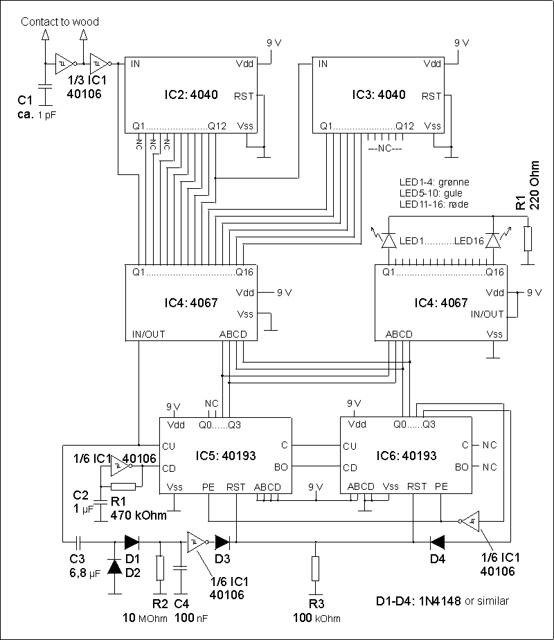
Because the resistance to be measured is very high for low moisture contents and low for high moisture contents, I have chosen to let the resistance of the wood be part of an oscillator and use the frequency (the measurement frequency) as a measure for the moisture content. The oscillator is a simple CMOS RC Schmidtt-trigger oscillator (1/3 IC 1) where the R is comprised by the wood resistance. The signal from the oscillator is fed to an 18-bit digital frequency divider/binary counter (IC 2+3) and compared to a reference frequency made by another oscillator of same type but with a fixed resistance (1/6 IC1). The result is shown on a 16-LED scale.The frequency comparison is performed in a special way: by an up/down counter (IC5+6). The divided measurement frequency is fed to the count-up input and the reference frequency to the count-down input. The two first bits of the counter aren't used. The next four bits (two from each IC) are used by the 16-channel multiplexer/demultiplexer (IC4) to select which output from the two frequency dividers (binary counters, IC2+3) to feed to the count-up input. A low count from the counter selects an output where the measured frequency is divided by a low number and a high count selcts one where it has been divided by a high number. In this way, the selected divided measurement frequency is kept as close to the reference frequency as possible.
Bit 3-6 of the u/d-counter are also used as a measure of the moisture content. They are fed to a 16-channel demultiplexer (IC7) and the outputs from the demultiplexer each directly drive a LED on the scale indicating the moisture content.
Bit 7 is used to pre-set the u/d-counter to prevent it from counting up to maximum and through to 0. Bit 8 is used in the same way to avoid it counting down to 0 and further to maximum.
If the resistance is increased very rapidly from a low value (e.g. if the electrodes are removed from the wood) it will take very long time for the reference frequency to count the counter down. This is solved by the reset circuit in the bottom (1/6 IC1) that resets the counter if there has been no pulses from the divided reference frequency for a while.
Diagram
Here is the diagram of the moisture meter. I will not promise, that there are no mistakes in the diagram!
Construction
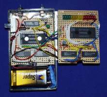
I have built the circuit on two pieces of Veroboard, that fits into a small box with a compartment for a 9 V battery. The LED scale i mounted in a row on one board and I have cut an opening in the box for the LED scale and for an on/off switch.The critical point in the construction is the measurement oscillator that is controlled by the resistance of the wood. It may be a little difficult to make it work so it is a good idea to build and test it before the rest. The capacitor in the oscillator is specified to 1 pF but it is very influenced by parasittic capacitances from the wiring. Therefore, it is necessary to adjust the reference oscillator. R1 in the reference oscillator may be replaced with a 1 or 2 MOhm trim-pot.
The pins that are to be pressed into the wood were made from two stainless steel screws that I sawed off the heads and turned the ends to needles.
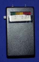
Below is a photo of the moisture meter and a photo of the electronics inside it. The electronics on the photo is slightly different fromt the diagram because it is from an older design.
| Search my site: |

